acadiel
1353
13
3

This modification allows you to add a SCART input to your legacy Commodore 1084S Phillips computer monitor. The modification has been detailed in recent videos by the Retro Channel. https://www.youtube.com/watch?v=r9xAZ8QvmiE
Also, Adrian’s Digital Basement: https://youtu.be/gISS9JsnRX8?si=2xwTI0xVKVs8uvSG
** Check the instructions on his video for your model - your model might be different! This is how mine was modified. **
Before the modification, most of these jumpers and components were visible in this one picture (five jumpers and two resistors). Two resistors (R210, R220) were missing, and one jumper (9290) needed a diode (1N4148 or 1N914) placed. Another jumper (9274) only needed a jumper. The other two jumpers were already there and didn’t need to be removed.
R210 - 390 ohm resistor
R220 - 1K ohm resistor
9290 - Placed a 1N4148 or 1N914 diode
9274 - Placed a piece of my leftover resistor trimmings.

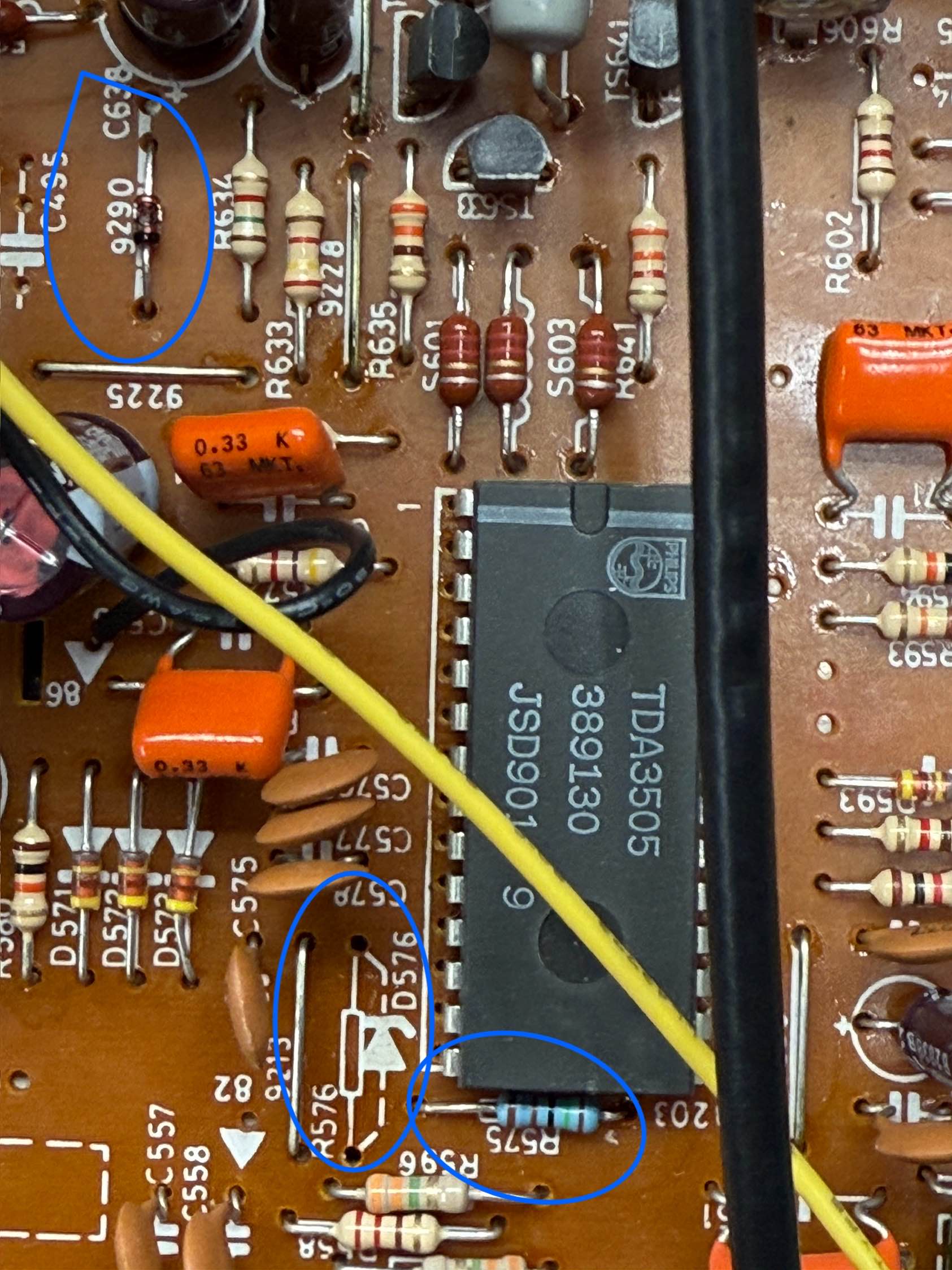
Before modification - 2/3. Note that R575 was an incorrect value and needed replaced and D576 currently has a resistor occupying it and needs it removed.
R575 - Changed to 1.5K resistor
D576 - changed to a 2.4V Zener diode (on Amazon for cheap or Mouser, DigiKey, etc.)

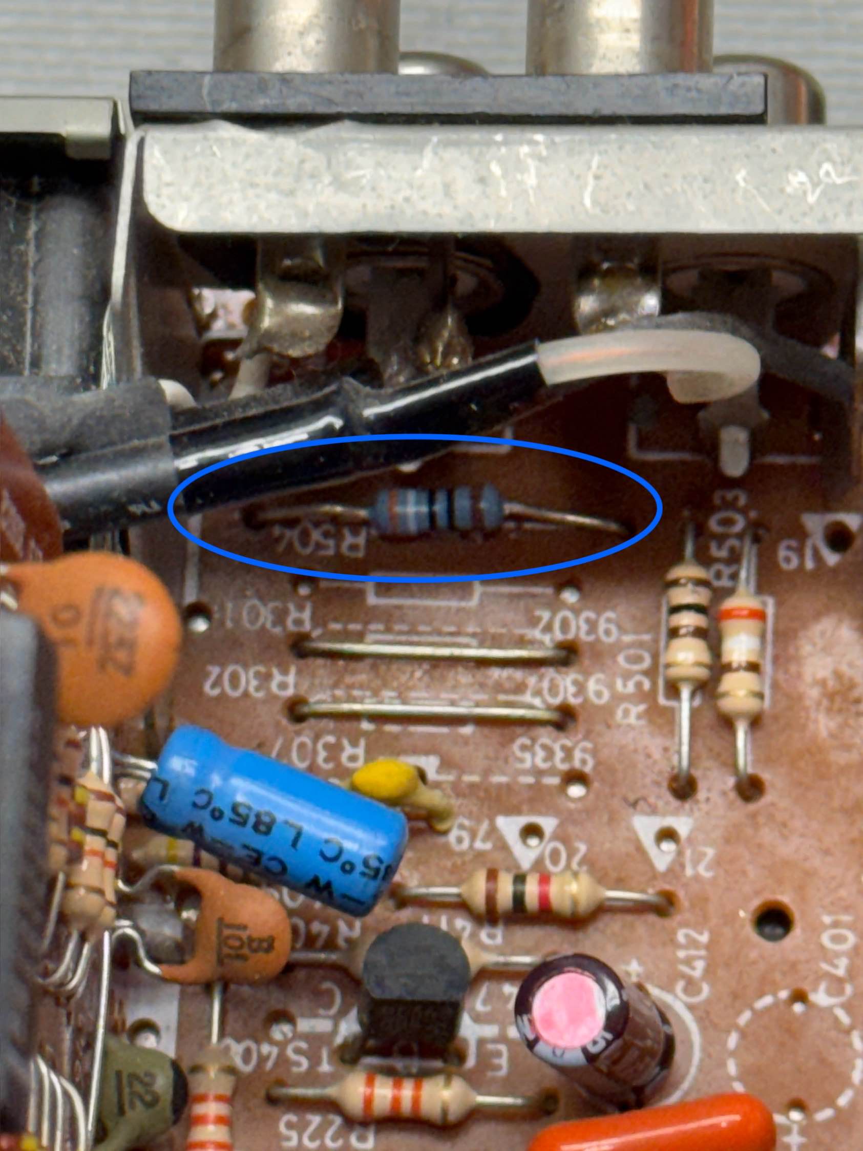
Before modification - 3/3. R504 is RIGHT BEHIND the audio jacks.
R504 - 390 ohm resistor

After modification 1: Resistors added to R210 and R220. Jumper added to 9274. Verified no jumper was installed in 9289. Verified jumpers already present in 9270 and 9275.
Again -
R210 - 390 ohm resistor
R220 - 1K ohm resistor
9274 - Placed a piece of my leftover resistor trimmings.
the other jumpers were already there
After modification 2: Installed resistor in R504
R504 - 390 ohm resistor
After modification 3: Installed 1N914 (1n4148) into jumper 9190 with band facing front of monitor. Removed resistor installed in D576/R576 and will be installing a 2.4V Zener diode in D576 with band towards rear of monitor. Installed new 1.5K ohm resistor in R575.

After modification, a diode and resistor in series (diode band facing away from the resistor) are installed with the resistor end connected to the middle of the VCR switch and the diode end to the front part of jumper 9290, towards the monitor front.
Diode: 1N4148/1n914
Resistor: 10K ohm

SCART: After modification 5, I soldered a jumper wire to the audio wire (white) on the board, unsoldering it from “2” and applying heat shrink. I then soldered the smaller jumper back to “2” and carefully soldered the SCART connector on top, avoiding breaking the wire.

SCART: Pre modification view of the SCART connector and the right channel “2” audio that is in the way.
Per the previous step, relocate the white wire referenced by the “2” on it by adding a smaller wire on it and soldering that wire back to “2”, encasing it in heat shrink to protect it.

SCART: This is how the smaller jumper wire looked where the “2” used to be. Note how it’s on the end of the SCART connector, so if you are careful, that small jumper wire will be safe.

My American 1084S-P had a resistor (R232) that I had to move to the PAL setting to get the SCART modification to successfully work. Thanks to @TheRetroChannel for figuring this one out!
75townecoupe
Are you keeping up with a Commodore?
DanielAsparagus
I just did my first speaker crossover. This is cool. Where can I find a tube amp kit?
PaperinoVB
It wold be more interesting if you told the reason behind those mods. What is the purpose of this?
acadiel
Thanks for the comment! They’re actually tied to the two YouTube videos I posted in the description. It boils down to adding a super sharp input to this retro monitor. Go take a watch and they’ll do the explaining better than I can!