rawkout1337
1333
35
2

Finished photo first, reuploading as I had a bunch of questions about how I built this.
I wanted a small, portable computer that I could use to debug code in arduino/raspberry pi projects that are installed in places that would be a bit precarious to bring a normal laptop. I’m aware how cheap I can buy a laptop. That is not the point of this project.
I also just really wanted to make a cyberdeck.
I designed the whole assembly in Solidworks around off the shelf electronics (with some minor modifications)
The main shell parts were 3D printed in MJF PA-12 Nylon, the orange accent pieces and black screen Bezel are PLA, and the white upper panel is laser cut styrene.
So lets dive in...

The first thing I did was source all the parts for the internals.
For the main compute unit I went with a Raspberry Pi4. I went with a Pi4 because a
Pi5 was a bit too expensive for what I was looking at and I don't need the extra performance for editing text documents. I did end up getting a fan/heatsink combo to better manage the heat the Pi4 generates.
The next thing I picked was a keyboard. I went with the cheapest mechanical I could find. I prioritized full sized keys as typing is the main use case for this deck.
I then sized a screen that had a similar height to the keyboard as I knew I wanted my deck to have a laptop form-factor. Picking a screen that was close in size meant that I wouldn't have any weird proportions to deal with when I was designing the deck. To connect to the screen, I got a HDMI to Micro-HDMI ribbon cable. This was entirely to save space in the housing as I anticipated there being a LOT of wires.
Because I knew there would be a lot of interference inside the case with so many wires shoved next to each other, I picked up a USB wifi card as well as an antenna extension cable. This gave me more freedom in where I could put the antenna on the deck. I also added 2xUSB 3.0 and 1xUSB-C extenders for the same reason. I also realized that I would be short 1 USB port with all my current peripherals, so I bought a USB hub that I would throw in the housing.
I envisioned there being a handle on this, so I sourced some bent metal cabinet pulls. I also used one as a wrist rest when typing.
I also wanted there to be some speakers on the deck, mostly for when I look up a youtube video to troubleshoot circuitry. I went with some incredibly cheap speakers that I knew I could drive with an old Adafruit amplifier board I had from a previous project.
After building the whole deck I realized that taking it apart to access the SD card was a giant pain, so I went back and added a Micro-SD extender. This enabled me to swap the card out without having to disassemble anything.

This just left how I would actually interact with the screen. I was inspired by retro computers and have always loved track balls, so I looked around to find a compact one.
I chose this one that Adafruit sells as it also had a board that handled mouse inputs as well.
After getting the trackball I realized that the housing was a lot bigger than the board on the inside. So I determined that I would scrap the plastic shell and print a new, more compact one. This also meant that I needed to source new mouse buttons...

I went with these PB86 step switches. I have always loved the look of these (they are famously used on 808 synths) and decided to use them in my build.

They have a weird pin footprint so I also purchased a breakout board that gives me nice 0.1" pins that are compatible with a bunch of wire connectors.

The last thing I knew I wanted to add was an easy power button/LED indicator.
The PowerBlock by PetRockBlock handles this amazingly and I highly recommend getting them for any Raspberry Pi based projects where you need to powercycle the board frequently.

With all the parts sourced it was time to start modeling. I designed the entire project in Solidworks.
I knew I wanted a laptop style device and that drove a lot of the design language on this deck. I quickly blocked in the components and started moving them around to get a better idea of the deck and how it would function.
One thing I realized fairly early on was that the location of the mouse buttons would be really awkward. Clicking and dragging would be almost impossible. I chose to move the mouse buttons to the back of the deck. This also freed up a lot of room on the face of the deck that let me center the screen and give the power button a similar bezel to the trackball.

Version 2. This model is a lot more detailed and includes mounting locations for all the parts, screw bosses, etc.

I modeled in most of the internal components. Doing this was incredibly valuable as a few times I caught collisions between parts that would have made the deck impossible to assemble.
I really prioritized ease of assembly and printability of each part. I knew that the black components would be grown in on an HP MJF machine so I did not have to worry about orientation or geometry as that machine can print pretty much anything, but for the orange pieces I did specifically design them so they would always be easily printable on an FDM machine.
Originally I was going to print the back vent component in FDM but ended up just growing that in MJF as well as it just barely did not fit on my Prusa.

By far the most important feature of the housing is the ability to fold closed for storage.
The way I modeled the deck was to have one sketch where I had a few key dimensions and relationships and could see how all the parts would relate to each other when the deck was folded/unfolded. This one sketch would drive every other subsequent feature. This meant that if I discovered something was interfering later in the design process I could go back and modify this one sketch and fix the problem.
As any Solidworks veteran will tell you, this (mostly) works without issue. I was lucky that I only had to adjust this sketch once and it only broke ~10% of the feature tree.

I knew I wanted the screen position to lock into place so I allocated room for a knurled thumb screw and a square nut. Tightening down on this screw would apply clamping pressure to the housing and keep it locked in place.
One change I would make is to increase the diameter of the hole the threads run through so I can add a bushing or sleeve over the threads so that the housing is not pivoting on the threads directly. This isn't going to be a huge issue short term, but over time that hole may wallow out and become sloppy.

For the other hinge I went with a simple FDM printed part that inserts in and is held in place with a few screws. I ensured that there was a hole though the center of it for me to route the USB-C cable that carries data/power to the keyboard.
This is another place where I am cautiously optimistic that this design will work. Over time bending the cable in that one specific location may lead to it breaking. I debated using a rotary contact, but the extra cost/size of incorporating one seemed like a bigger hurdle than just changing out the cable if it breaks.

The next biggest hurdle was assembling the trackball/mouse buttons. I de-soldered the mouse switches from the PCB and added wires/connectors that let me connect to the new switches. I went with connectors rather than solder as I fully anticipated having to disassemble everything later and boy am I glad I did!
I completely mis-measured the board for the mouse buttons so I had to do some last-minute modifications with my Foredom to get everything to fit. This meant I had to assemble/disassemble that board several times.
The actual trackball assembled just fine... except for when I realized that one of the USB wires had broken loose. So I had to disassemble the whole thing again to fix that.

All the components shoved into their home. I barely had enough room to get everything in there and very much regretted not adding another 10mm to the thickness of the back vent, especially when I went to install the Micro-SD card extender and found that it was 5mm too long...
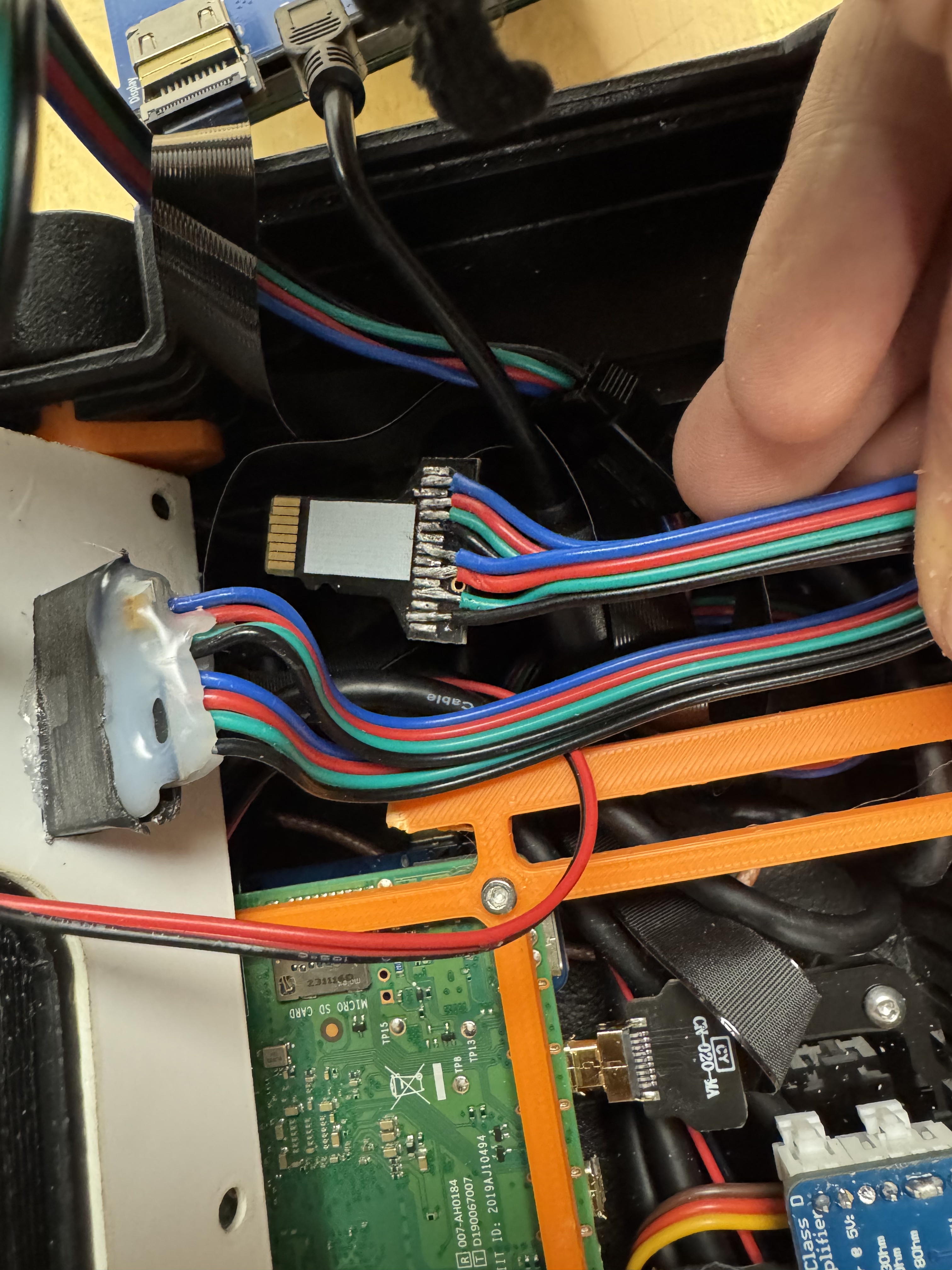
So to fix that I cut the back of the extender housing off and replaced the fragile ribbon cable with a more robust cable. After an hour of fine tuning the soldering, I flooded both connectors with hot glue to prevent breaking and shoved them back in the case.

The screen helps hide a lot of the mess but that rats nest on the left still makes me really sad.

But when its all screwed together you would never know!

Portability was a key part of this project and I feel like I really nailed it.
The six screw holes on the back of the case allow me to further expand the deck's capabilities. I am already on making a mount for a USB battery pack so that I can power the deck away from a wall.

The two USB ports are easily accessible on the side of the unit and the USB-C port allows me a ton of flexibility on getting power to the pi.

The "grip" style mouse worked out fantastic and I am incredibly glad I did not go with the front facing buttons. Using the mouse this way feels very intuitive.
My only complaint is that the track ball is too twitchy so I had to turn the sensitivity way down. But thats fine, I mostly navigate text files with they keyboard anyways.

Overall I am incredibly happy with this deck and I love the look it has.
I've already had a bunch of coworkers stop and ask me about it and they are blown away by it. Hope y'all are too!
sometimesidontevenknowwhyibother
First: F'ckin awesome. Second: I'd love your work to be rolled into something like the sBitx. I often use my sBitx (which is an SDR) as a standalone computer as well, and would love to have a built in keyboard that doubles as screen protection. Which actually gives me an idea now...
theamountof
DisposablePersonality
I have absolutely no need or use for something like this and yet I want one. Because of reasons.
rawkout1337
That may have been the main motivator for me building it lmao
bigdix69420
What do you use it for? Looks amazing BTW. Well done
bigdix69420
Apart from debugging or is that it? Could it be used for anything else? Are rasp pi fast enough for emulation?