ririlot
797
13
3

I have a DJI Mini 4 Pro and something that always annoyed me about the controller was that it only has a lanyard mount at the back.
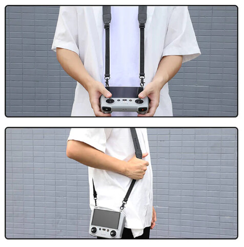
This makes it hang down like a handbag and means I have to support it at the front when flying.

There are trays that mount to the controller but they increase it’s bulk quite considerably. Ideally I want something that mounts a strap here.
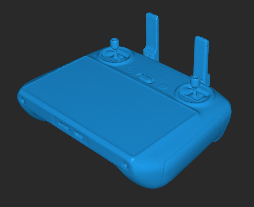
In order to create the part, we first need to create a scan of the DJI RC2 controller. It doesn’t need to be mega-detailed but we might as well show off Miraco while we’re doing it

Another view of the scan

Side view

Getting it in to CAD
There are several ways we can get this model in to CAD. We could re-draw it from section sketches like I’ve shown before but for this project, we’ll use a different way.
Triangles to quads
I want to create a T-spline model of the controller in Fusion360. Unfortunately, the mesh to T-spline converter can only deal with quad meshes and the output of Revoscan (and all other scanning tools really) is triangles. We can covert the model to quads using a nice, free tool called Instant Meshes: GitHub - wjakob/instant-meshes: Interactive field-aligned mesh generator

Let’s load up our scan; click Open Mesh:

Our mesh is loaded and ready for conversion:

At the moment, our target vertex count is way too high at 100k. Fusion360 will have a fit. We want that around the 10k mark ideally. Move the slider to 10k:

Next, hit Solve under Orientation Field
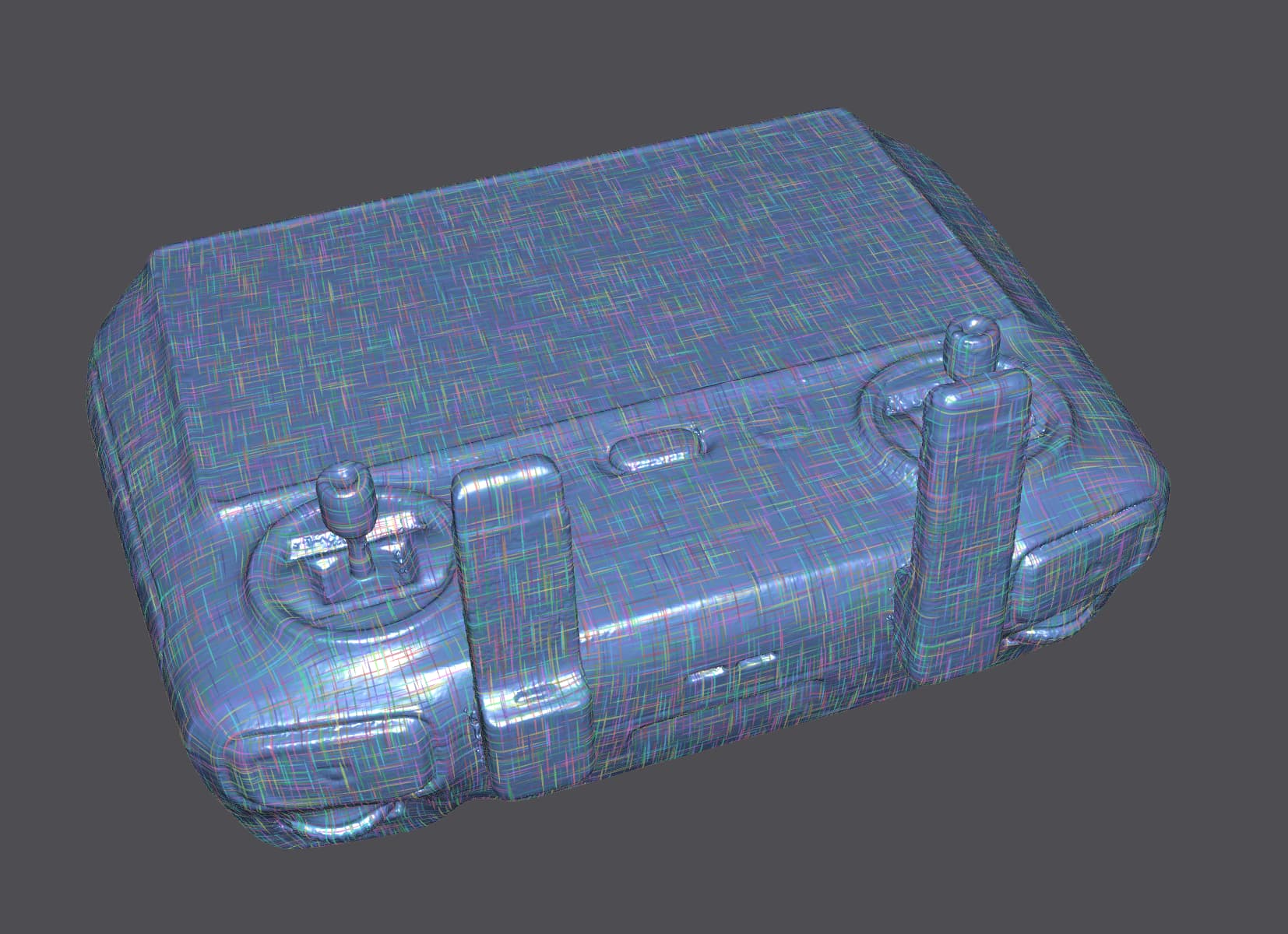
Our mesh will have lots of pretty colours on it now.

Then, hit Solve under Position Field
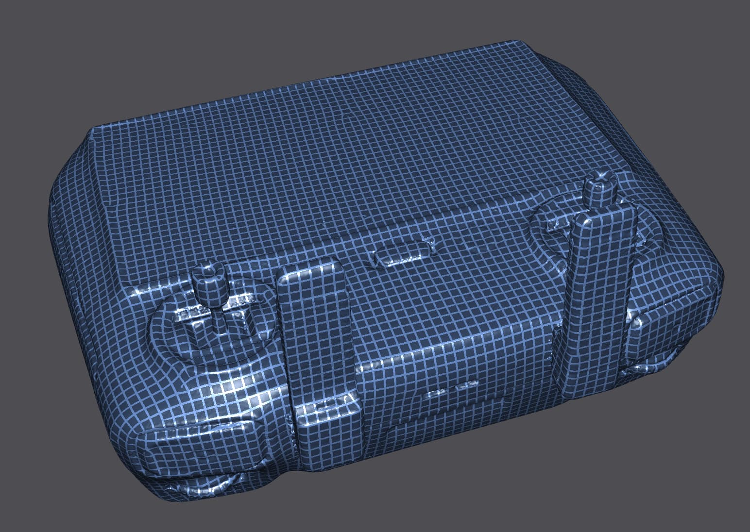
And now our mesh is all squares:

Hit Export and choose Pure quad mesh (this will ensure that all the facets are quads and that no triangles remain.

Finally, Extract Mesh

And Save

Now, over the Fusion360:
Create a new project, import your quad-mesh and orientate it so that it’s aligned with X, Y, and Z.

Next, under the surface tab, select New Form

Then hit Convert

We want Quad-mesh to T-Spline

Hit OK, and Fusion will chew on it for a while, then hit Finish Form

We now have a defined solid in Fusion that we can do all sorts of things with:

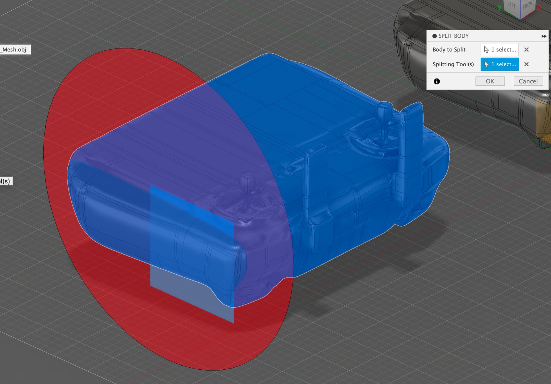
As you can see, we can cut it up just like a normal solid

OK, back together we want to make a copy of it

The new object, we want to scale it to make it bigger. I want something that will fit around the controller but follow the controllers lines. Let’s make it 1.1x bigger. Make sure to scale from the origin rather than a corner.
Now, let’s cut it up and make the rough model that we want:

More cutting

Even more cutting

Man, can we stop with the cutting?

Now we have our rough model, let’s put it over the 1.0 scaled original model and then use that model as a tool to cut out from our new part:

We end up with this, ready for an attachment to be added:

A quick bit of CAD and we have our part:

This is what it looks like rendered in Fusion:

Rear view

Let’s print it and see how it fits:

Like a glove

And that is a quick and dirty way of getting a scan in to CAD. See more of my Miraco showcase here: https://forum.revopoint3d.com/t/andy-beta-miraco-showcases-of-bones-shells-art-design-modifications/
Back Miraco on Kickstarter here: https://revo.ink/3Fj4pYP
jon5465
As an architect who does a lot of 3D modelling / diagrams / 3d printing this was fascinating. 👏